Rudder not following command
Today I want to write about a steering gear issue I encountered on board. Steering gear is considered a critical equipment and the issues related to it must be tackled immediately.
PROBLEM
The port steering gear rudder indication is not following command set on the Follow-up tiller or the Autopilot.
For example, if the FU tiller is moved to 20° port, the rudder indication would move randomly anywhere between 10 and 40°.
Meanwhile, there are no issues with the starboard rudder indication.
TROUBLESHOOTING
I will eliminate all the electrical components and cabling common to the port and starboard steering gear as a potential issue because, if any of the components common to the port and starboard rudder was defective, the issue would manifest on the starboard rudder as well.
I pulled out the drawing and identified all the electrical equipment that is NOT common to the port and starboard rudder.
For example, Follow-up amplifier is not a common part because both port and starboard steering gear have a dedicated FU amplifier. On the other hand, FU tiller is common to both steering gears.
After inspecting the drawings, I found out the following electrical equipment is not common to the port and starboard steering and thus qualifies as a suspect that is causing this problem:
Rudder angle indicators, FU amplifier, CAN bus distribution unit, power changeover relay, pumps, solenoid blocks, variable frequency drives, feedback signal converter and feedback unit.
Ok, is there anything I can eliminate quickly from this list?
Yes, power changeover relay – its purpose is to switch from main to backup power supply in case mains fails and it is not a culprit in this case.
Other than relay, I cannot rule out anything with certainty.
Can I quickly test some equipment to make sure it is not causing his issue?
Yes. There are 2 pumps (each pump is run by a dedicated variable frequency drive) for each steering gear. The issue persists regardless of which pump is running so this rules out pumps and frequency drives.
My next suspect was the feedback unit – a potentiometer mounted on the rudder stock. As the rudder moves, potentiometer’s resistance changes. I’ve observed resistance as the rudder was moving and it was fine – there was nice linear correlation between resistance and rudder position.
In ideal world, I would now be able to quickly and easily read inputs and outputs from the FU amplifiers, CAN bus distribution unit and feedback signal converter and see if there is anything wrong. They are communicating through CAN bus (Controller Area Network), same way electrical components in a car communicate. Unfortunately, at that time, I had no way of accessing that CAN bus.
I then decided to swap port and starboard FU amplifier to check if it will solve the problem, but it didn’t.
After that, I swapped CAN bus distribution unit and there was again no improvement.
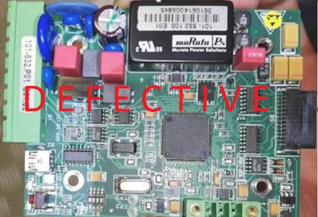
Finally, after swapping feedback signal converter, port rudder started behaving normally and the problem transferred to starboard side.
A feedback signal converter, as it is named in the drawing, was a PCB that was converting potentiometer’s resistance into CAN bus telegram.
After about 10 days, we managed to get the new PCB and then I had to first connect to the CAN bus (which also required a special hardware and software) and then assign a CAN bus address and calibrate the new PCB. After a detailed testing, I could confirm the problem was solved.